By Ron Ruiz & William Pimblott
The Ghost Was Not At 29 Megacycles.
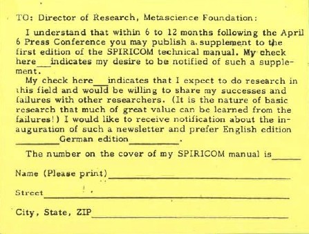 Did you know there was more than one version of the Spiricom Tech Manual? Did you know there were updates issued? For the first time anywhere, you will have the opportunity to download the complete Final Version of the Spiricom Tech Manual with all the updates included.
If you have been following our recent Spiricom articles, you have come to realize that there was more to Bill O’Neil’s setup than previously known or reported in John Fuller’s book or the Spiricom Technical Manual that is currently available online.
You really – really need to listen to the audio report on the Spiricom setup as compiled by Metascience Research Director Bruce Dapkey in January 1982. It explains so much about the revised Mark IV. To do so: Click Here
For those that are unfamiliar with the recent discoveries, let us recap.
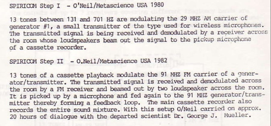
Over the last few decades the accepted accomplishments of George Meek, Metascience and Bill O’Neil’s efforts at achieving two-way real-time communication with a deceased scientist identified as Dr. Mueller occurred at a frequency of 29 Megahertz (29 megacycles).
Documentation has proven that the frequency credited with the 20 hours of recorded communication with Dr. Mueller was in fact at approximately 91 Megahertz.
That’s right. Bill O’Neil operated the Spiricom device in the FM range of 91 Megahertz and not 29 Megahertz.
As with any creative effort, changes along the way can be expected. The Spiricom system of 1980 that most people think of with the bulky Hammarlund SuperPro 600 High Frequency Multiband Receiver, HP 608 Signal Generator, TS418B/U and other gadgetry; was not the finished product in 1982. For your review, Dr. Ernst Senkowski provided the following observations:
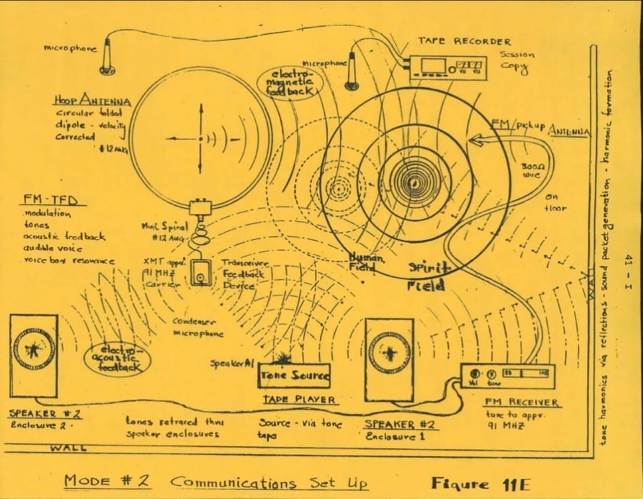
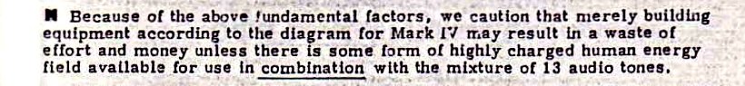
Also, while the world thought Spiricom was a straightforward assembly of a receiver-transmitter augmented by a set of 13 special tones, Bill O’Neil employed a familiar theme used by Jules & Maggy Harsch-Fischbach and others at the time: A feedback loop system.
Bill O’Neil discovered a way to use an audio and electromagnetic feedback loop that also took advantage of one’s natural invisible energy field; much the way placing your hand near a radio antenna will pick up the impedance of the body.
As William Pimblott puts it; a feedback loop takes advantage of many principles that modern ITC researchers have forgotten. From reflection to refraction to deflection to time delay to beat frequencies; a feedback loop provides more raw material for voice formulation and trans-communication. Add to this the targeted Spiricom tones and the outcome as Bruce Dapkey claimed….”was powerful”.
So…was the new and improved Mark IV setup complicated? Not by a long shot. Below is the parts list as described in the updated edition:
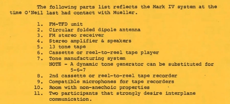
How cool is that!! As we run through the parts list, you’ll see how the Ockham’s Razor theory of “simple is usually best” comes into play.
Item#1: FM-TFD stands for Transceiver Feedback Device. This is nothing more than a wireless microphone repackaged in a project box. If you want to try your hand at this…depending on if you want something modern, vintage or a Hanna Montana wireless mic like I have, there are many to choose from in all price ranges. According to the diagram, the TFD was attached to the dipole antenna via a short coil of 12 gauge copper house wiring. Since a wireless microphone has an adjustable frequency, 91MHz was probably chosen as an inter-frequency for Bill O’Neil’s specific area.
Item#2: The Circular Folded Dipole Antenna. The reason Bill O’Neil chose this type of antenna was to multiply and match the impedance of the 300 Ohm antenna used for the FM Receiver. The Dipole antenna was made using two and a half feet of 12 gauge copper house wiring. With the TFD attached to the dipole, the antenna acted as a secondary transmitter.
Item#3: FM Stereo Receiver. Nothing special about this piece of equipment.
Item#4: Stereo Amplifier and Speakers. This may sound confusing but all this means is the amplifier was part of the FM Receiver.
Item#5 – #6 – #7: The 13 Spiricom Tones. The combined 13 tones were played by way of a cassette recorder.
Item#8: 2nd Cassette or Reel to Reel Recorder. The purpose of the second recording device is to record your sessions.
Item#9: Compatible Microphones. Pretty self explanatory. Digital recorders had not been invented yet so a microphone was an essential component for recording.
Item#10: Room With Non-Anechoic Properties. Basically what this means is a room with as little sound absorbing material as possible…such as carpeting on the floor, cloth furniture or curtains.
Item#11: Two Like Minded Participants. One premise on the success of Spiricom was the idea that a person with strong psychic abilities stood a better chance of establishing trans-dimensional contact than the average person.
Here’s how the new Mark IV acted when up and running:
There are still many unanswered questions. I do know that there was a period of time when the old Mark IV was used for communicating with the likes of Doc Nick and Dr. Mueller. I also know that shortly after the Washington D.C. press conference, George Meek went on a world tour promoting the Spiricom device. I also know it didn’t take very long for George Meek to realize the Mark IV did not work as he thought it would:
Anyways…here is the link for the Complete Spiricom Technical Manual with all updates. You will notice the main updates are in Yellow. The PDF is searchable and has been formatted in case you want to print out a hard copy for yourself. Do a double sided printing and the charts will be in the correct orientation. All I ask is that you credit Ron Ruiz, William Pimblott and iDigitalMedium as you begin to share this on your own websites. ~ Thanks…..Ron
Complete Spiricom Technical Manual
P.S…..its even autographed 😉